
When starting the build of INDININI I wanted flexibility in the means of control, display and alerts. I looked through several options, and even considered coding things myself and then I stumbled across ESPHome which led me to Home Assistant. Who would have thought a framework for small esp32 devices and home automation would work so well for a boat?
The initial intrigue was that ESPhome supported so many different types of sensors. I was excited to think of the ability to have moisture sensors, humidity sensors, light sensors etc all controlled from one area. Little did I know that once I educated myself enough on the entire framework, it could and would take over the entire boat!
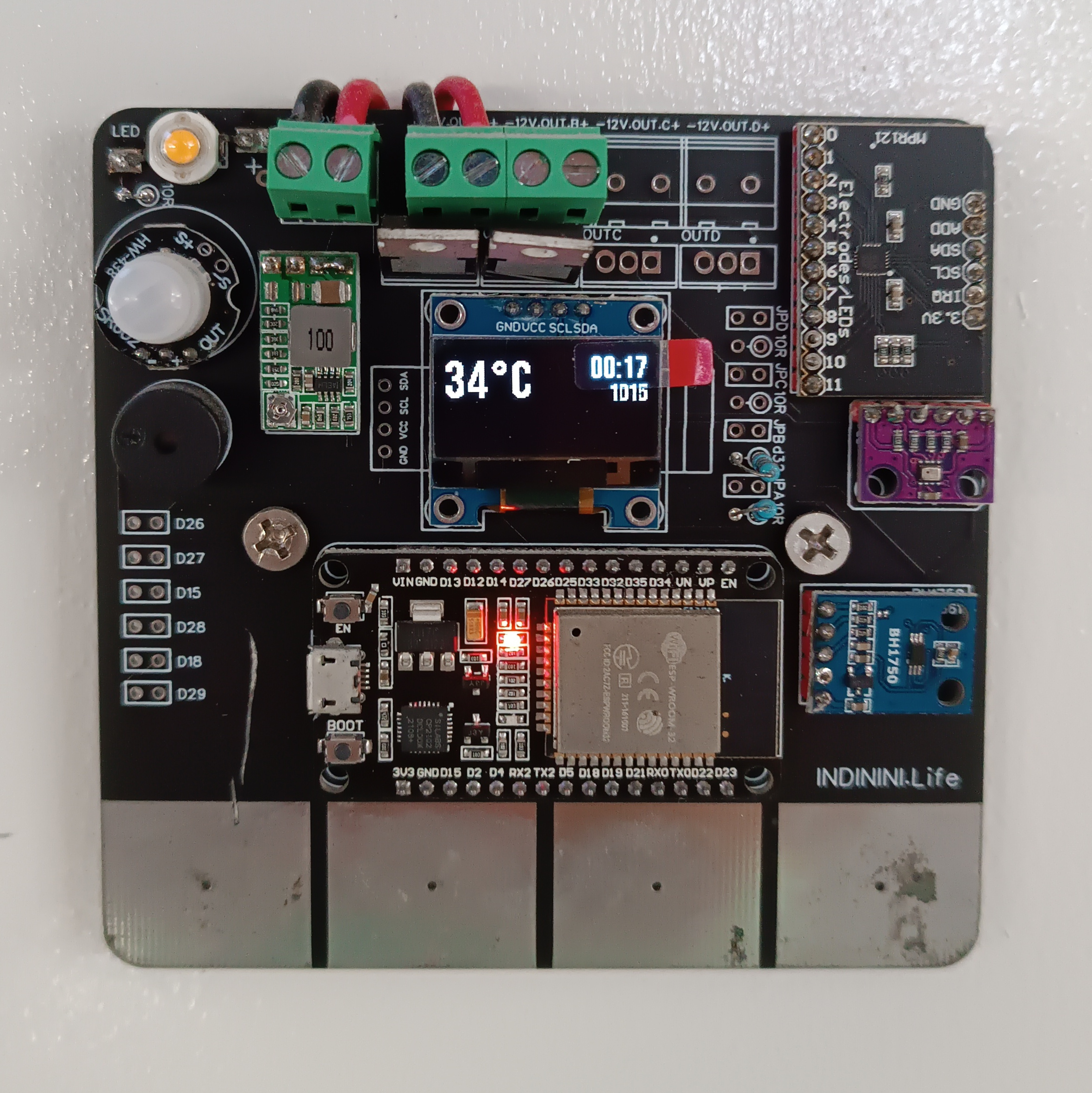
I had an old raspberry pi 3 so I added some repositories and installed Home Assistant. It was slow, and hard to update versions but got the job done. I was then using the ESP8266 as I was more focused on power consumption than ease of use and flexibility. I used these and designed a PCB for light switches that included the esp8266 dev kit, light sensor, motion sensor, humidity sensor, a .96inch OLED display, 1watt LED, touch sensor, MOSFETs and a small power supply. These are images of v1.1 and v1.2.
Light switch version 1
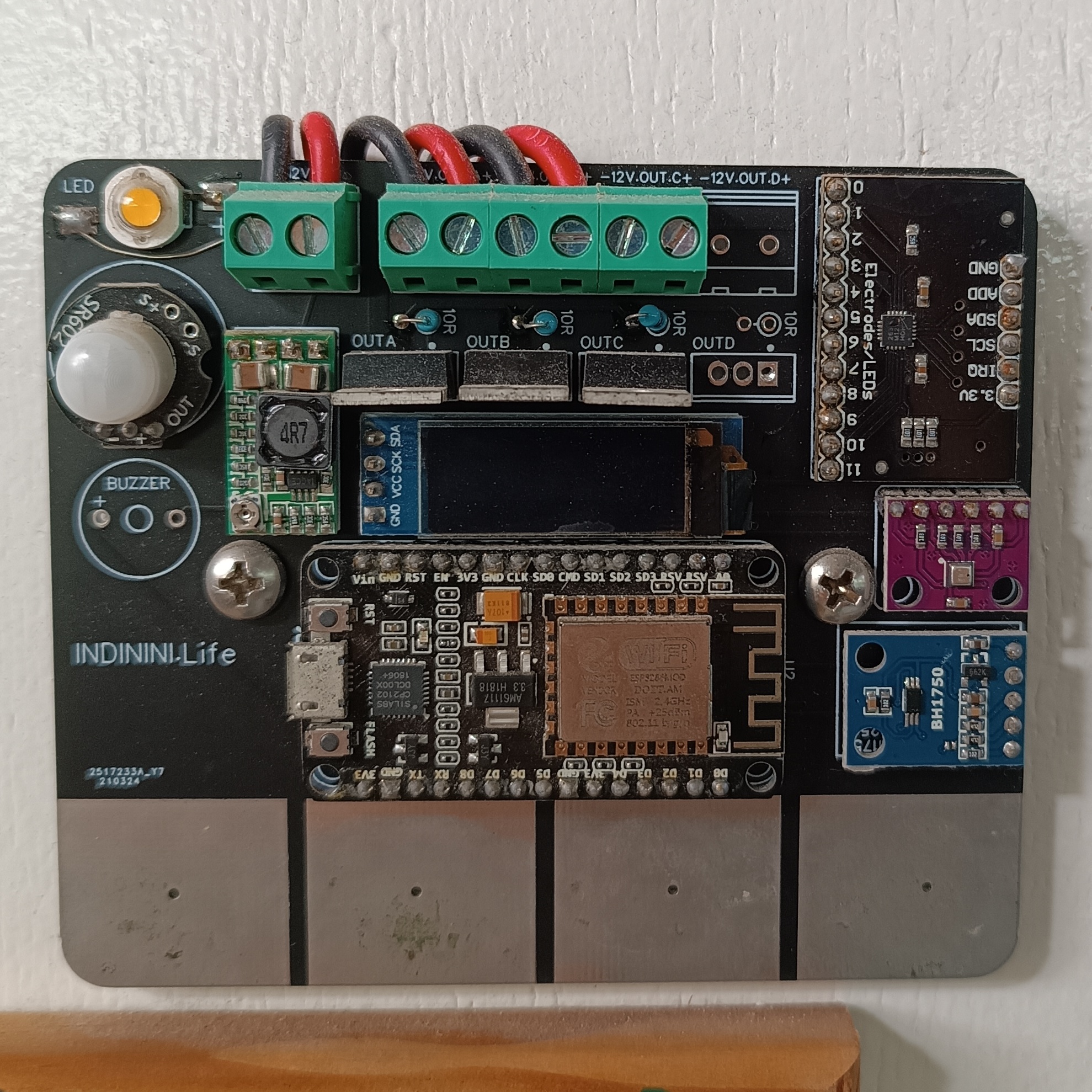
This is the first version. The touch sensor idea started because I desired to make a touch light switch for India and Nina who were going to be 3 and 4 years old when we started sailing. I wanted them to be able to touch a painted light switch at their height and turn on and off the lights. I had done tests mixing graphite and acrylic paint to see if the capacitive nature of the switch would work…it did! By the time the boat was done, this idea had “expired” and India was tall enough to reach the light switch touch pads. I created the PCB with pads directly on the board which was easy to make.
The use of the PCB in this way worked in isolation from the Raspberry Pi instance of Home Assistant. This means even if the connectivity to the rpi was down or the RPI was off, one could still turn the lights on and off. The other reason for configuring the flow like this is to suit flexibility and consistency in the future. This means that the power came to the PCB, and the wire then continued to the light. This is a normal wiring scheme and if so desired, the PCB could be removed and a simple on/off switch be put in its place.
Having a ‘smart’ light switch offered the following bells and whistles…
- if motion is detected, and the lumen is below a certain level, turn on the led for 10 seconds. A nice to have when you get up in the middle of the night.
- lights can be controlled by the Home Assistant app. Kids always like to play with the lights.
- the screen showed the temperature, humidity and pressure. While working on the boat I could see I was working in 45 degrees heat. Reminded me it was time to quit!
- motion sensors provide the ability to send alerts of activity
- and besides the actual functionality….it was nerdy fun!
Home Assistant image
For those who are starting with Home Assistant, it is a no-brainer to flash the image onto an SD card and put that card into an Rpi. The os and app image version of Home Assistant is sooooo much easier than the alternative of installing on top of a Raspberry Pi install. Updates are easy, integrations are easy, and ESPhome updates are easy. Don’t waste your time…just do it!
Light switch version 2
It took some time and some learning but after a summer of sailing, back to work for a while, and finding the time to evaluate requirements, I started working on V2. I found that I didn’t like soldering little bits onto boards. I also saw that some of the components were not necessarily top quality from Aliexpress leading to issues. Version 2 was going to include the bare minimum that I needed based on my experience with v1. I set out to design a new PCB using info gathered from v1. No soldering…make JLCpcb do it all, cover things, keep it simple, bigger touch pads. I gained knowledge on power supply requirements and what is needed to put an esp32 directly on a board and skip the devkit. I kept the idea of the motion sensor but replaced the single white LED with an RGB LED and got rid of the other sensors, light, humidity and temp. This is the result.
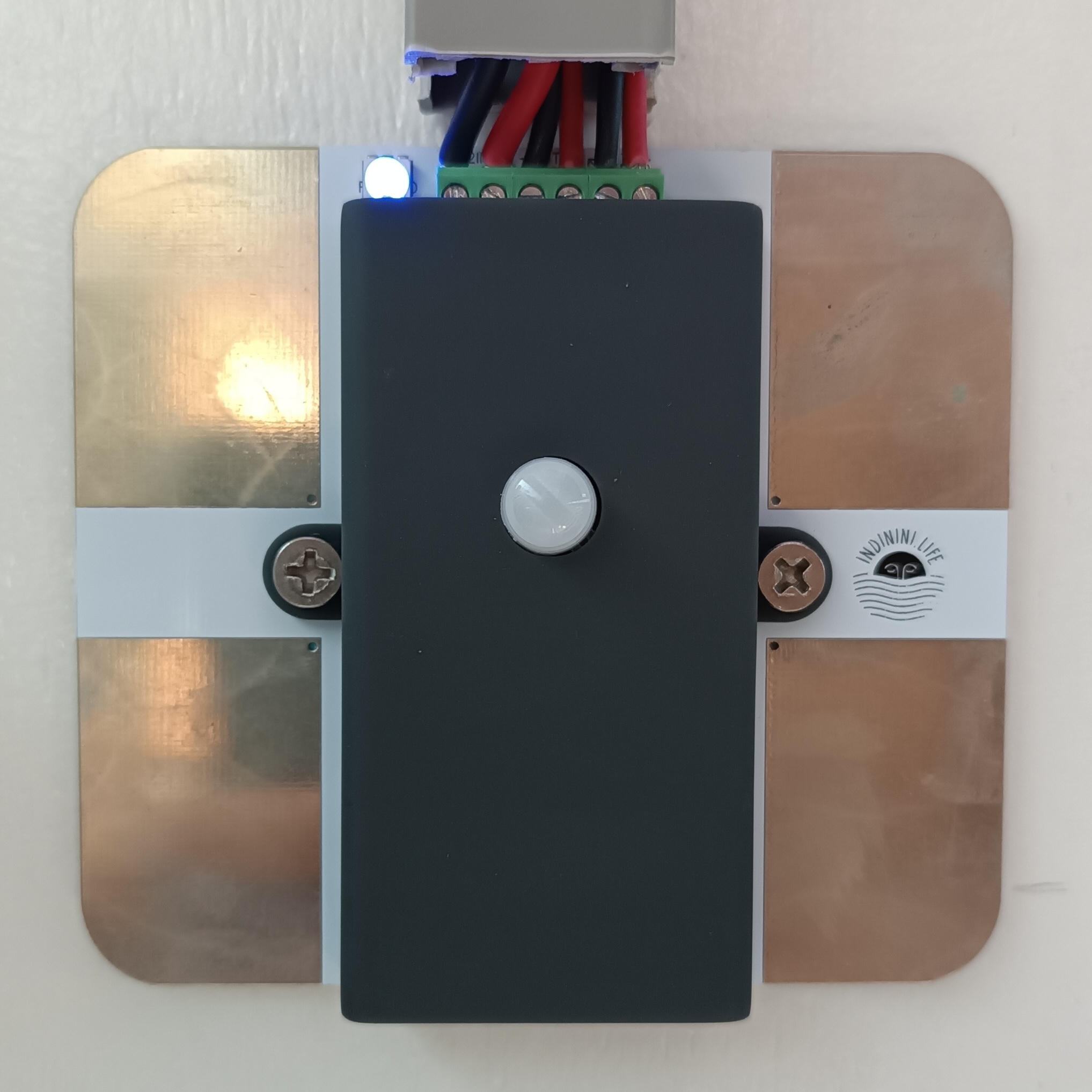
Maybe not the ‘prettiest’, but its only v2! Already have ideas for v3.
SignalK Integration
INDININI has a airmar nmea2000 depth sounder. It is the 12-degree version as it is mounted on the curve of the forward hull. The n2k cable runs aft and plugs into the hat of the Raspberry Pi4 that runs the pypilot. This Pi4 runs SignalK. Simply put, SignalK is a broker of information. Many people in the sailing community are already using SignalK. It brings in info and outputs info. It accepts the depth details from the sensor and sends this to the mqtt broker of Home Assistant. Home Assistant then records this and displays the details. Even the very popular boating app, Navionics can be configured to pair a device and read information over wifi from SignalK running on a Rpi. The main configuration on INDININI is to gather AIS information using the MAIANA project send it to SignalK and send it out to Navionics to show ship details.
Motor integration
The motor is a Netgain Hyper9 electric vehicle motor. It is designed to be used in a car and has a CAN bus interface. CAN Bus is a reliable network used in vehicles. Getting the RPM motor information into Home Assistant and ultimately the Influxdb was crucial to achieve the desired chart. In the summer of 2022 when sailing tech parts on INDININI were limited so i opened storage containers to see what i had. I used a solder breadboard to connect an esp32 with an MCP2515 CAN bus interface. I was not sure if it would work but with a bit of sailing time on my hands i gave it a go. I contacted Thunderstruck who where very helpful in providing the necessary details required to read the CAN Bus info. The result was successful. I used ESPHome to show the output and shortly afterwards deciphered it and displayed it as needed.
Motor BMS integration
The BMS is a Dilithium Design for EV motors. It also connects to CAN. The motor and BMS however need to be on 2 separate networks, so I got the solder iron out and made a second ESP32 and MCP2515 for connecting to the BMS. Once again Thunderstruck provided the necessary details for reading the BMS information. This included things like voltage, charge state, and individual cell voltages. From there a little math and we can display average cell voltages, high and low voltages.
Zigbee integration
Zigbee was one of the last integrations included in the INDININI setup. It connects to the water sensors. Many sailors do not have any water sensors in their bilge. Others i have come across have one that goes off and is independent with no management console. There are no alerts if batteries are low or dead. The Zigbee integration with Home Assistant is easy. The water sensors are small and run of a lithium battery. They are approx $10 USD for each device. There are 5 water sensors in INDININI. They work GREAT.
Victron
Yes of course we need to integrate the Victon shunt and solar controllers into Home Assistant. There are libraries here that contain all that is needed in order to configure an esp for serial connection between the MPPT controller and output to Home Assistant. The real-time display is nice as it immediately shows in the dashboard. The recording of history is great to see displayed in the charts and graphs of power generation, voltage stats and usage.
The dashboard
At a glance with ultimate detail. This is the best way to describe the options you have when using a Home Assistant dashboard. See what you want to see, how you want to see it. Sure it might take a bit of reading and learning but the alternative is to either not have what you want or hire someone to do it for you.


Influxdb
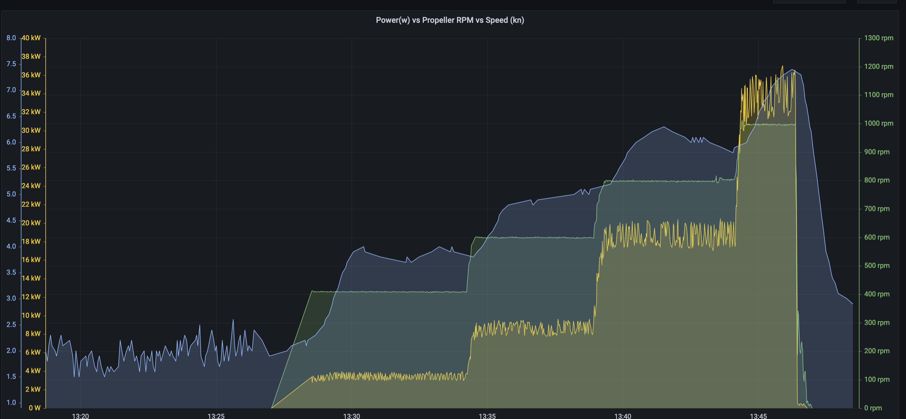
Influx is a time-based database. Home Assistant has easy integration and with a few clicks you can start recording EVERYTHING. The biggest issue is knowing what results you want to get out of the data you collect. For me, I knew exactly what I wanted to gather. From the very first thought around putting an electric motor into INDININI, I wanted to know speed/rpm/power. Integrating all of these into one graph was the ultimate goal. The only outstanding variable on this now is to add a variable for solar power generation. Not an insurmountable task, just has not been done yet. Current stats can be seen on the post regarding Power RPM Speed.
DIYBMS
The initial setup for house batteries in INDININI included one of the ‘dumb’ bms from Daly. This was a 250amp inline bms. It got the job done, but it had no management interface, app or visibility of voltages etc. The newer ones do. I had 5 DIYBMS designed by Stuart Pitway made in early 2024. I installed one in INDININI in March. What I saw as soon as i turned it on shocked me. INDININI’s house battery consists of 4p 8s. They are Calib LifePo4 cells. 3.2v 200ah. I opened up the interface and saw a huge range in voltages between the cells. This means there were 2 cells that had less resistance resulting in charging and discharging faster than other cells. These cells got higher voltages faster and ultimately the victron MPPT saw this higher voltage and moved to a float stage to stop charging. Unfortunately the other cells were not fully charged which means the overall battery state probably never got over 80% charge.

Installing the DIYBMS included the installation of a 500amp ev contactor. This is like a big relay. The DIYBMS is not an inline bms like the Daly version, it monitors and has relays to run other components.
The nice thing which Stuart Pitway has integrated into the DIYBMS is the necessary API config for integration into Home Assistant. The home battery details can now be seen directly in the Home Assistant interface. In addition, alerts can be configured for charge levels, high and low-voltage cells. These alerts have yet to be activated because the house battery is now additionally configured with an active balancer that the DIYBMS turns on as soon as the difference between cells is greater than 10mv. It works fantastic. The capacity has greatly increased. During 2 months of sailing in July/Aug of 2024, there were a couple of accounts where the solar panels were not charging the house battery for 4 days and there was still power to run things.
Important Alerts
Do you want to know if there is water in your bilge? motion in your boat? shallow depth? motor too hot? rpm too high? cell voltages to high or low? No problem! How do you want the alert…sound? email? telegram? flashing light? No problem! Home Assistant can do it all.
The nice thing about this and one of my biggest concerns from the beginning was reliability. Is it going to be like Windows OS and we need to restart every day? NOPE. The ESP32 devices are highly reliable. The Raspberry Pi based on Linux is highly reliable. I have been using Linux since 1996 so I had a certain level of comfort knowing HASS was running on Linux and the sensors were based on ESP32 which have a reputation for stability.