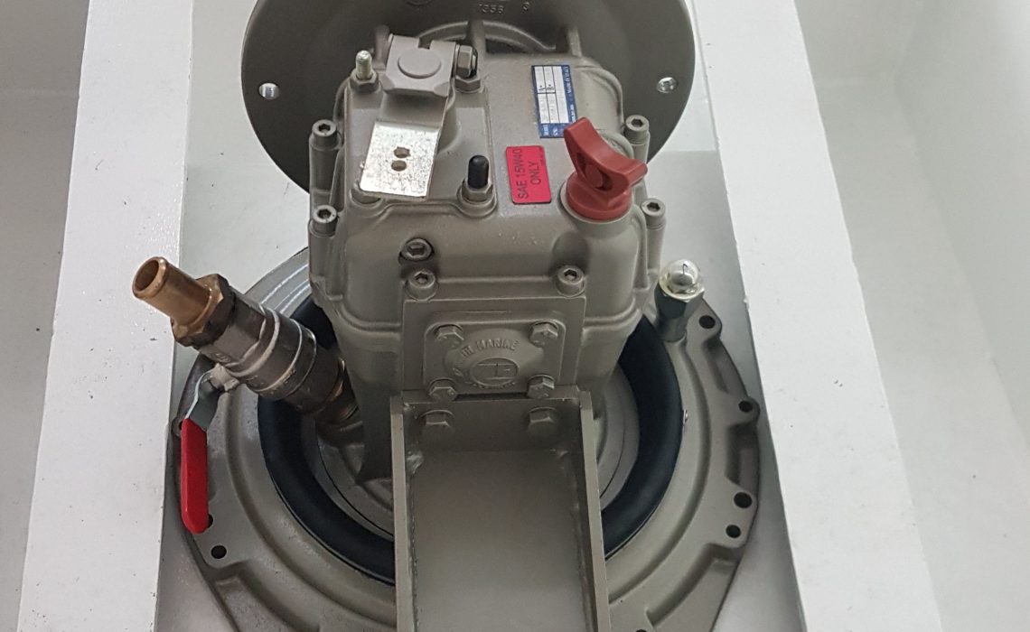
ZF SD12 Saildrive and Bruntons autoprop ecostar for sale
In order to maximize the advantages of using an electric motor, I have decided to replace the sail drive with a shaft drive. This will allow a custom gear ratio to maximize the efficiency of the motor and allow forward and reverse directly from the motor.
Install date: 2021
Launch: Dec 2021
Hours: 40
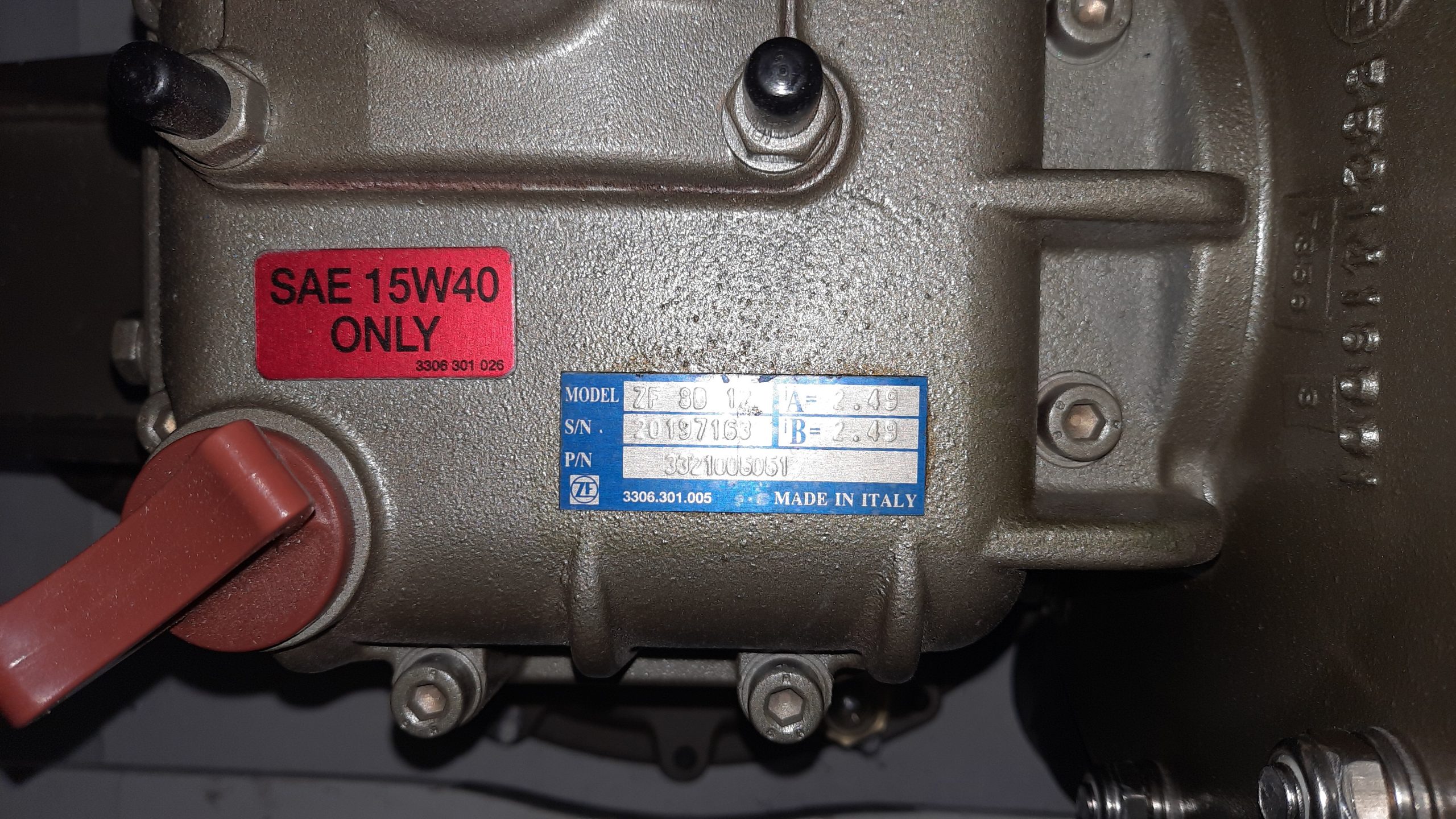
Ratio: 2:49:1
ZF product website: https://www.zf.com/products/en/marine/products_64503.html
Condition: Excellent. Like new
Propeller: Bruntons autoprop ecostar APS-H5-506mm
Bruntons product website: https://bruntonspropellers.com/autoprop/
Location: Greece
Available: March 2025
Reason for sale: INDININ has an electric motor. Due to gear ratio, hull design and shape, we are not able to fully take advantage of all aspects of the electric motor using the sail drive.
Price: Sold together EUR6000.
Contact me to discuss the price or sale of the sail drive and propeller separately.
Contact Dennis. dennis@indinini.life. WhatsApp +852 9128 4245
INDININI was in the water for 2 years. She is currently on land. During the time in the water, careful inspection of the anodes on the sail drive and propeller was noted. The sail drive anode has a minimal reduction. The propeller anode was replaced 2 times and each time the anode was < 50% reduced.
Original install details
The design of INDININI from Marc Lombard Yacht Design included a sail drive instead of a shaft drive. Both designs have pros and cons but in our case, the pushing factor to move forward with the sail drive was to keep the design as is and not require any changes. The other thing we really wanted to avoid in using the sail drives was vibration. Ironically, vibration issues are most relevant for diesel engines and after our electric motor started spinning we realized it didn’t vibrate at all. Yay!
There was a lot of learning required in order to feel comfortable when ordering the EUR3000+ ZF sail drive. The main concern was how it was going to work together and correctly with the electric vehicle motor. Along with the usual web searches and research, there were also calls with Brunton’s propellers to ensure what we choose would be compatible with the propeller. In the end, it was decided that since the spec’d Yanmar diesel for the boat had similar RPM targets as the electric motor and that the sail drive had been used with the diesel engines for many years, our electric motor would be ok.
With the pandemic in its beginnings and the world unsure of what issues it might bring, we ordered as much as possible for the boat including the saildrive. the result was it sitting in the container for more than a year before getting put in place.
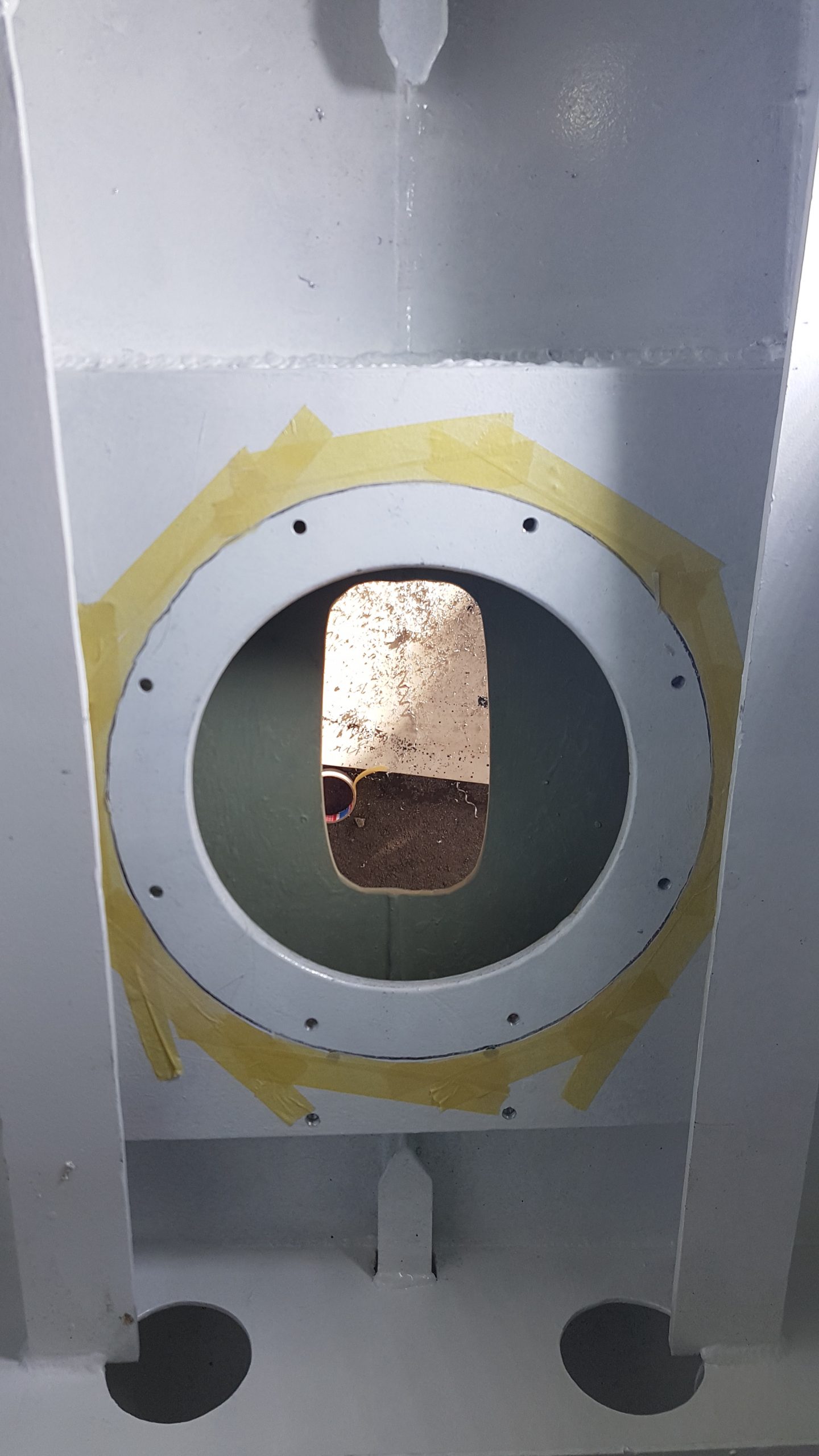
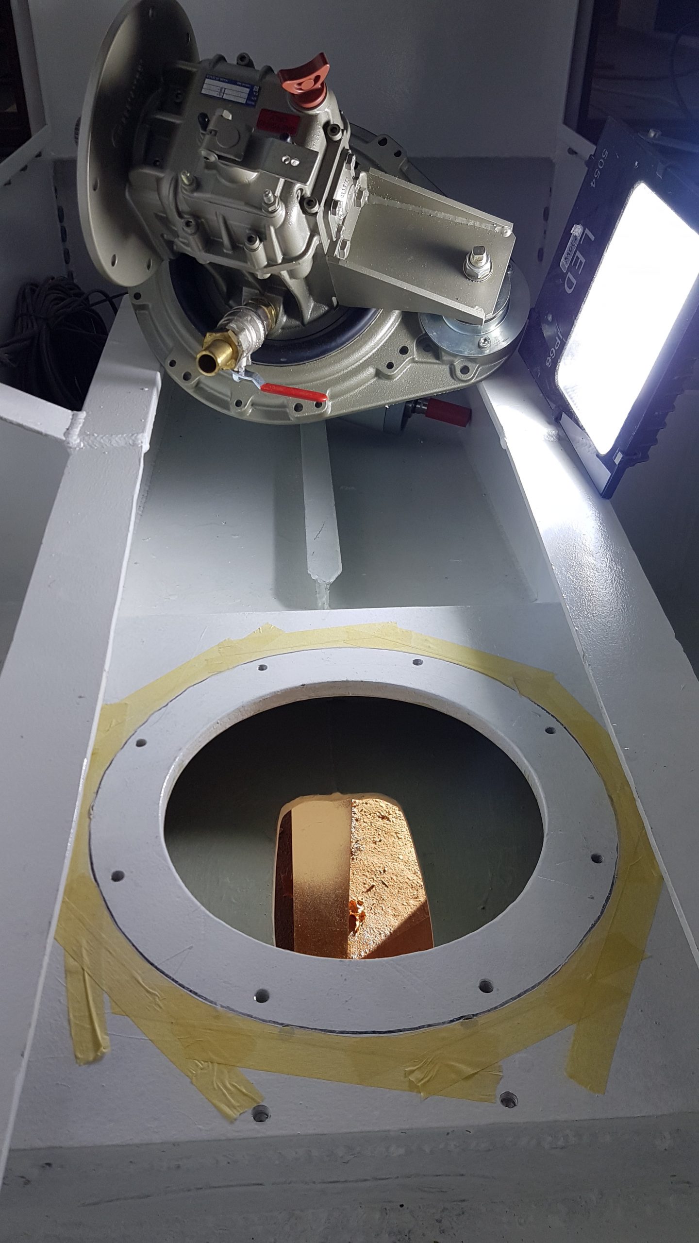
The first step was to weld in the mount and cut out at hole in the hull for the leg of the saildrive. The mount consisted of 3x16mm thick pieces of aluminium. The following is a long pieced together raw video of the process. It was a hot day, dressed in shorts in a tight area. Not pleasant but got done.
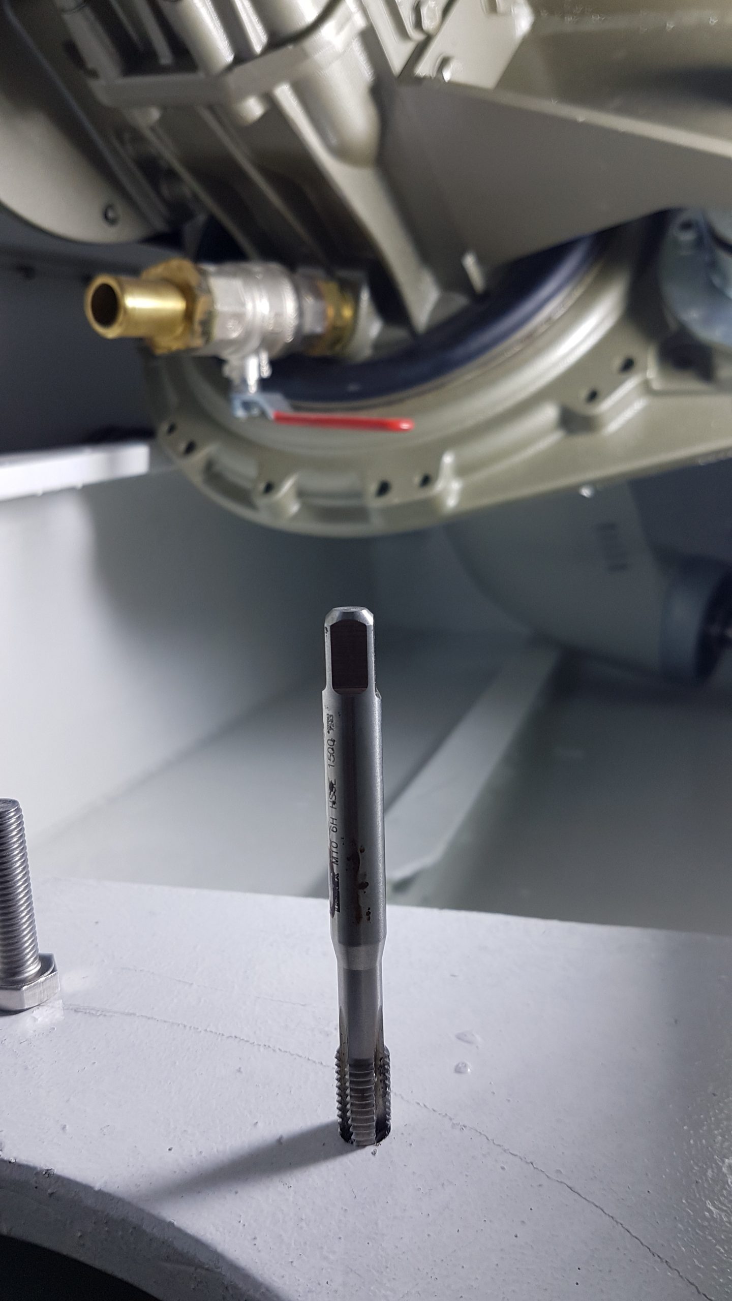
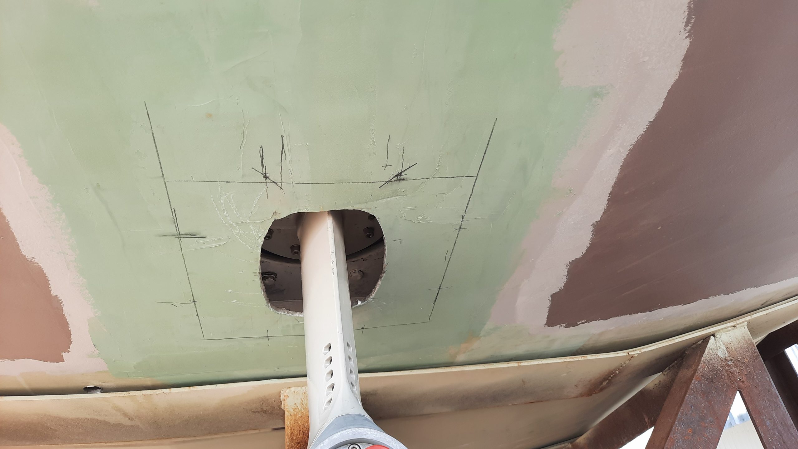
The next step after painting of course to make it look pretty was to set the sail drive in, mark the mounting holes, drill and tap them.
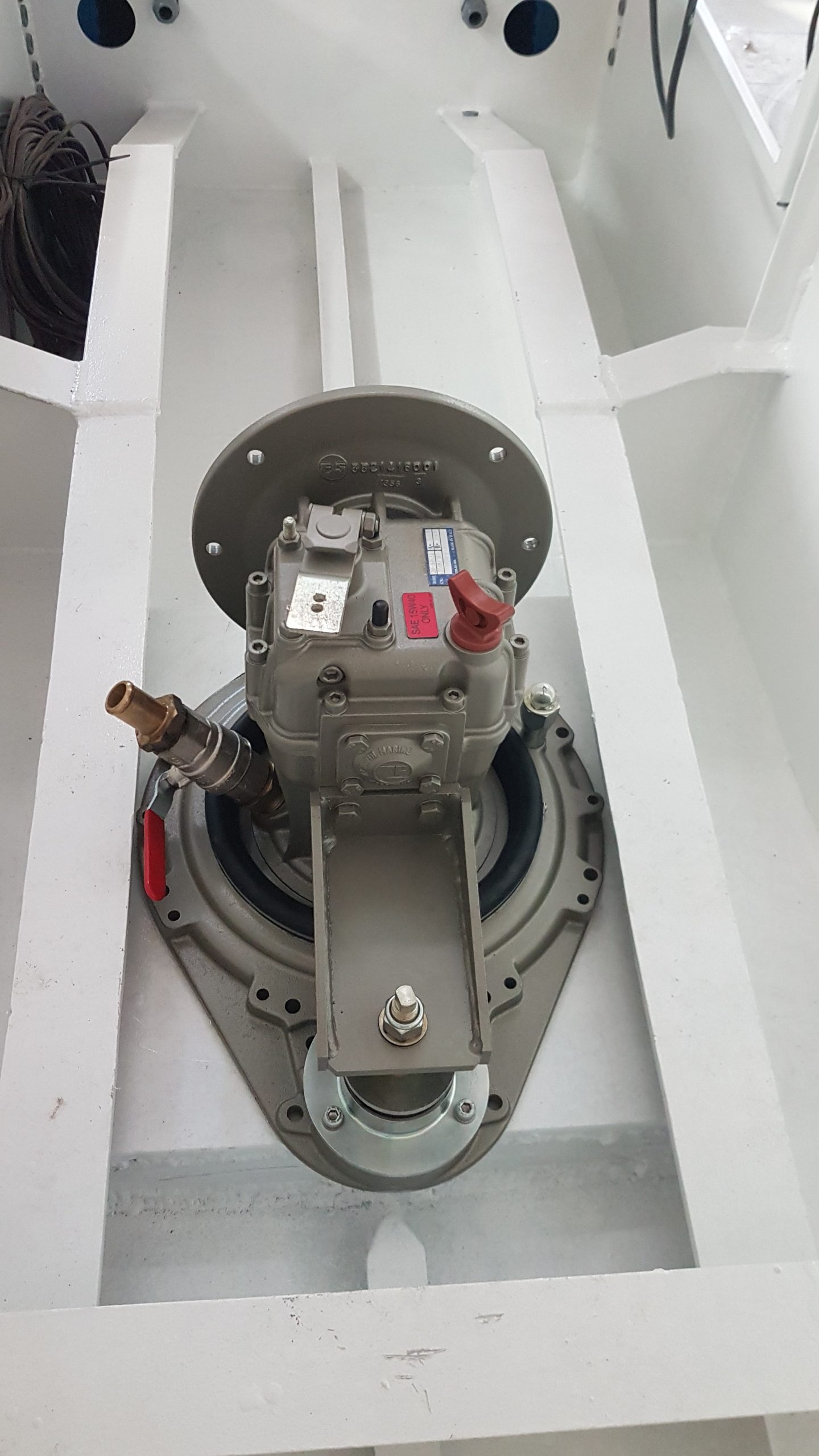
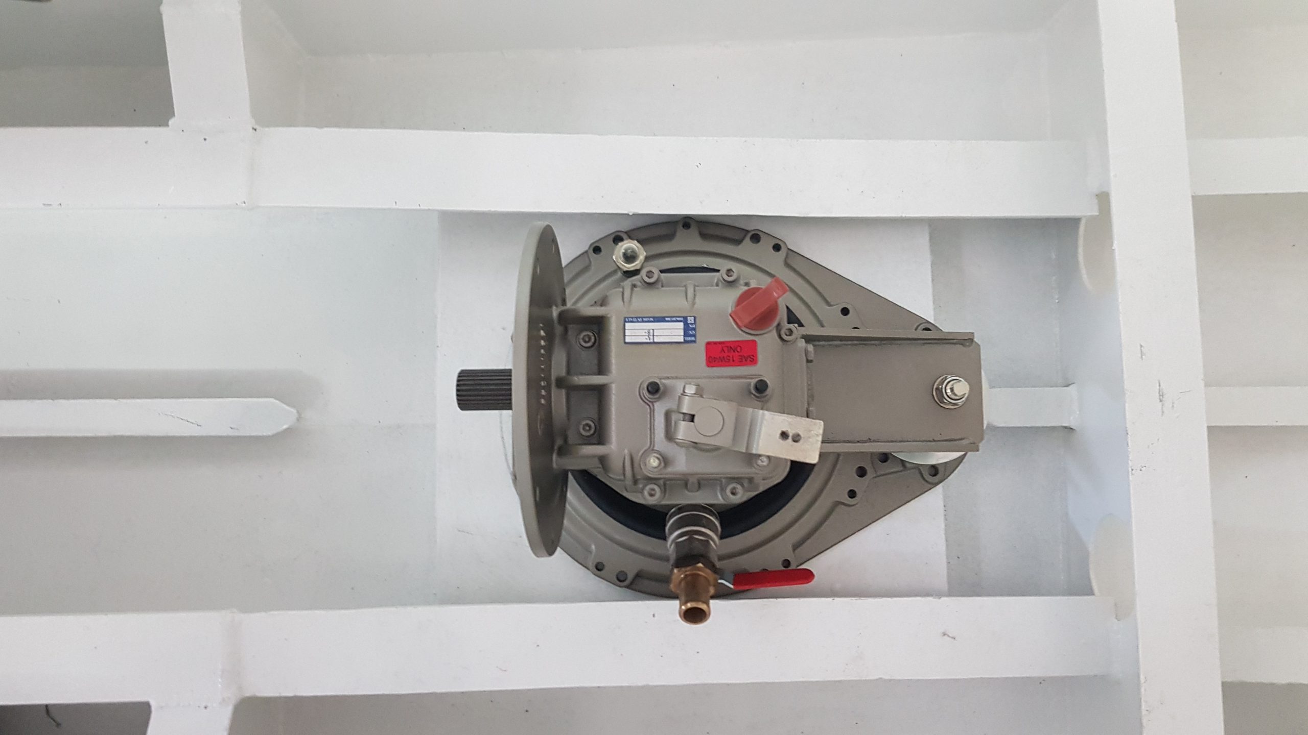
The bolts were threaded from outside to inside. The first time doing this I had not used any sealant on the bolts and was done for testing and to make sure everything fit together. I did tighten the nuts on top of the saildrive only to find out that when tightening them, sometimes it started turning the bolt as well leaving a gap between the head of the bolt and the outer saildrive mount. Note to self…make damn sure this is taken care of before final installation.
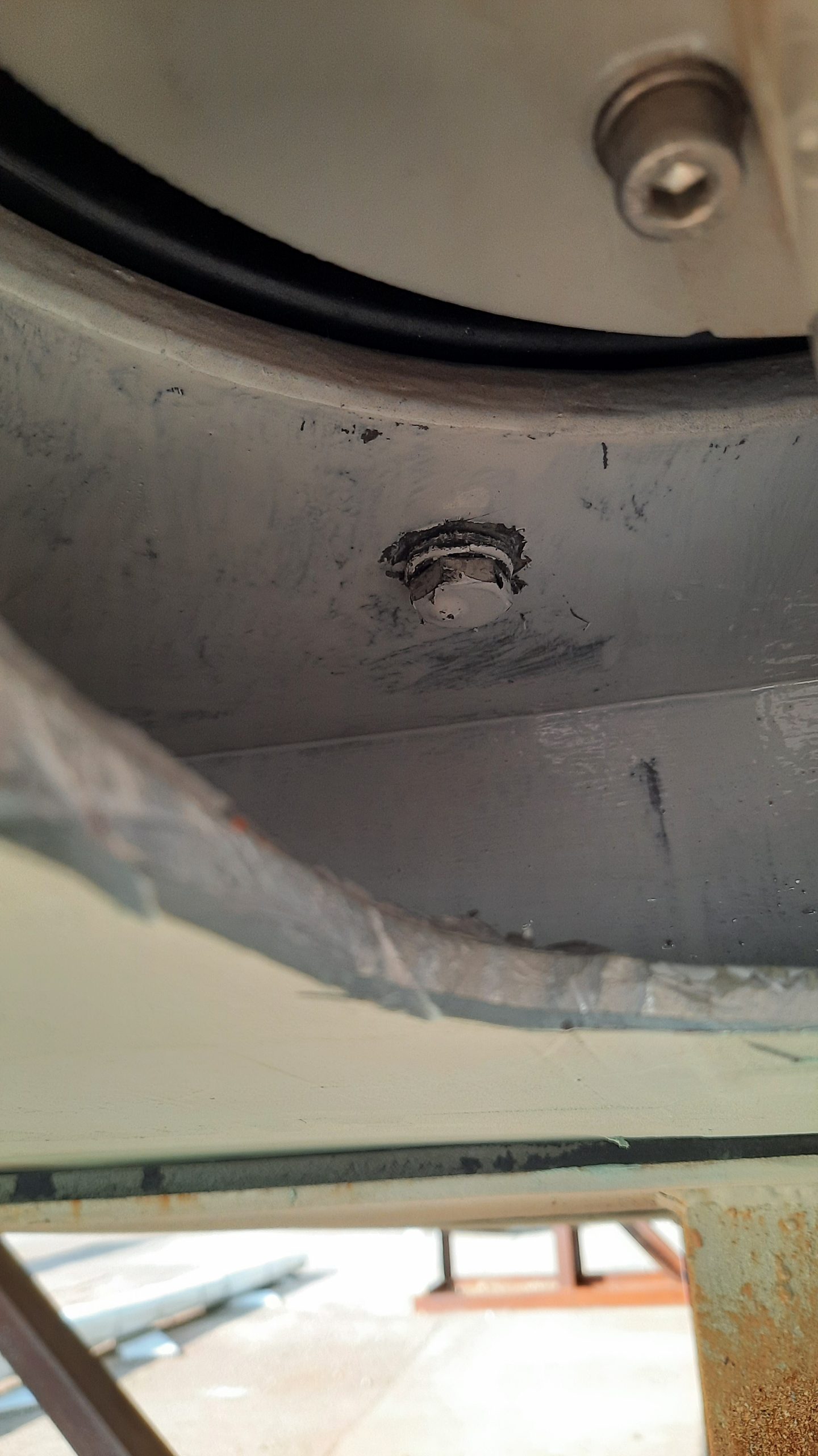
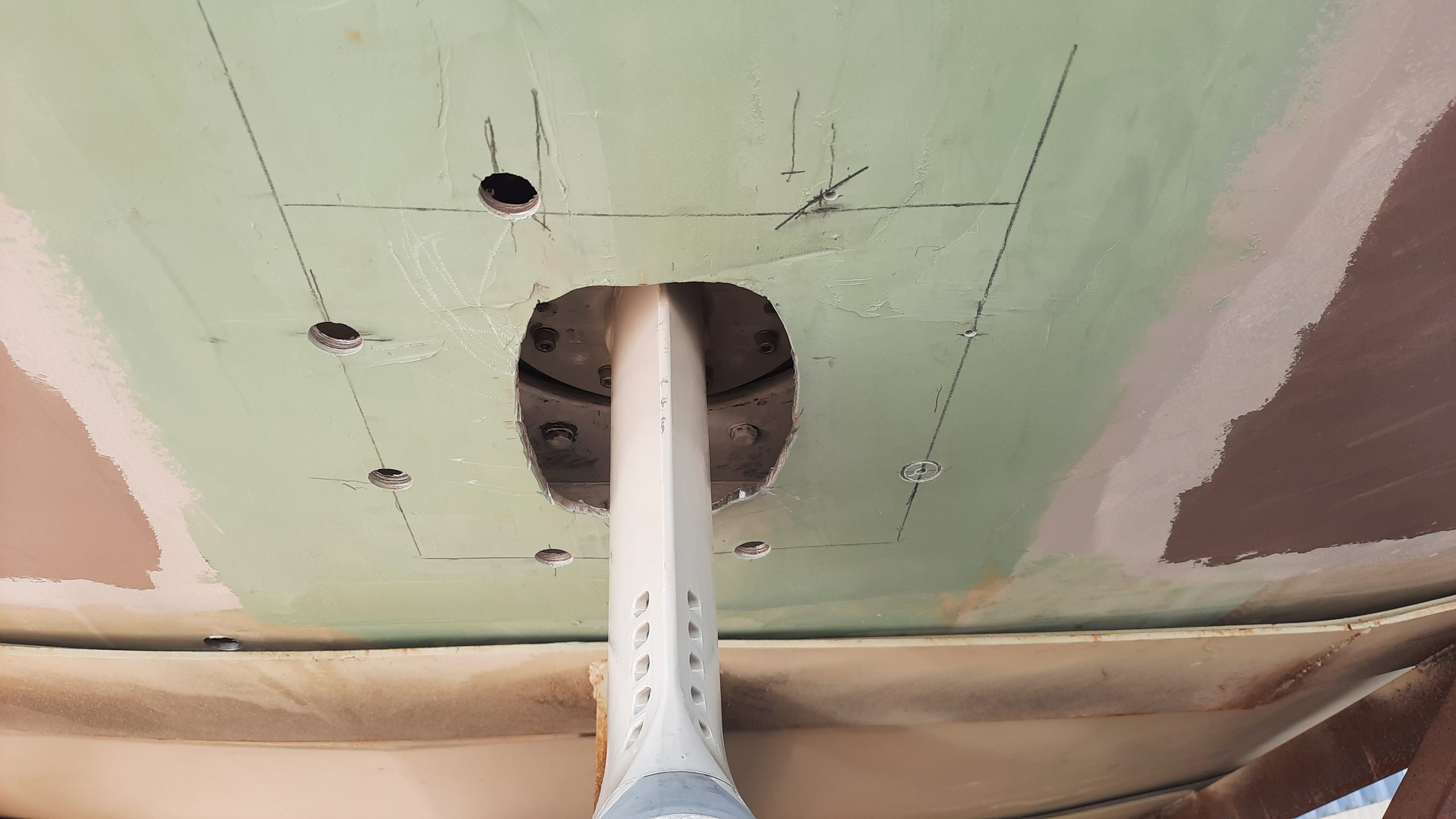
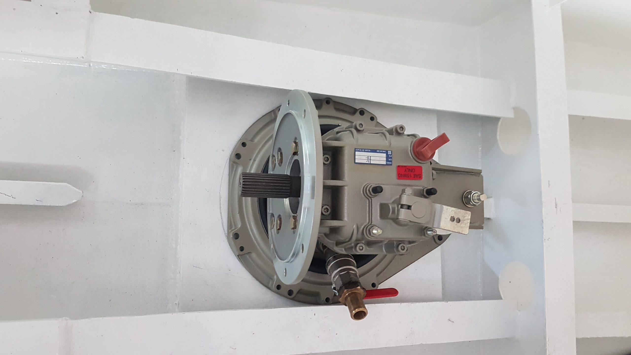
There are a total of 6 x m10 bolts to secure the sail drive to the mount. Since the holes and threads were done by hand, they were not angled at a perfect 90 degrees. When the drive was put in and secured the first time, it was summer and hot. It was 6 months later that I had to finalize things when it was cold. I found that trying to pull the sail drive out to sort out the bolts were going to be a struggle. For this reason, I measured, marked and drilled holes in the bottom of the hull which would fit the socket and allow me to remove the bolts one by one. I did this and made sure I used LOTS of tefgel, or in my case, tef45. These holes also allowed me to have someone hold the bolts while I tightened the nuts from the top.
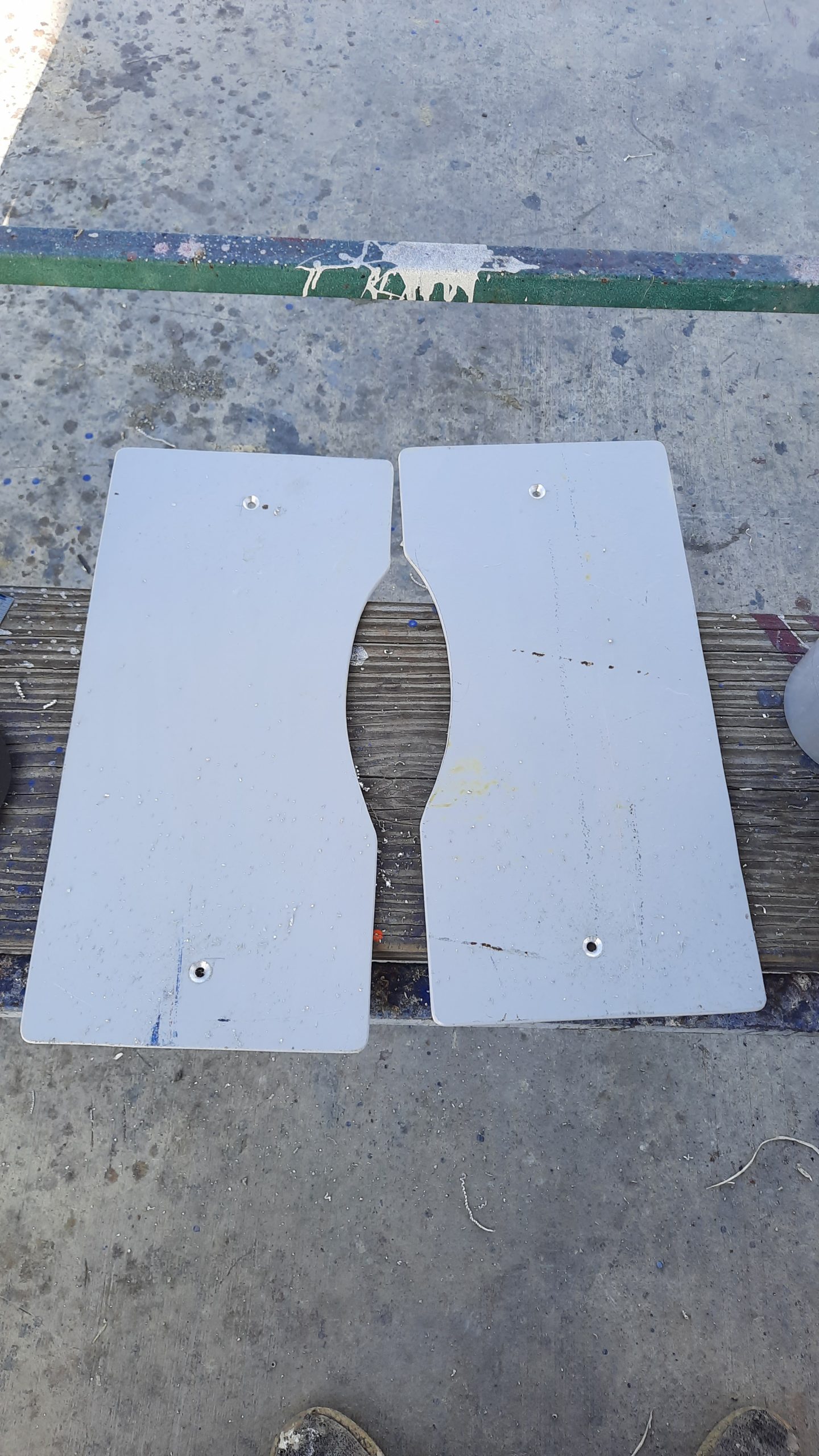
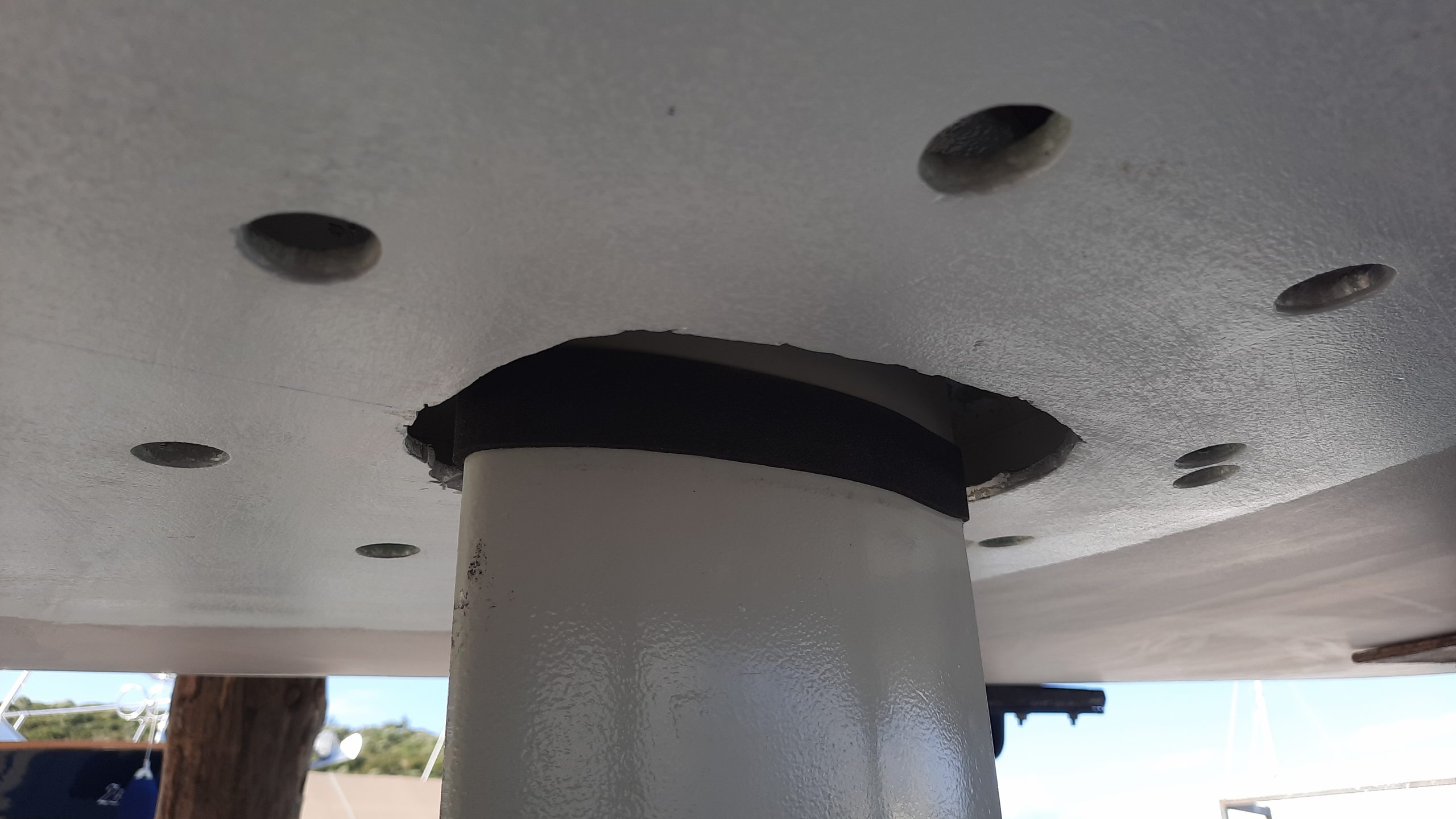
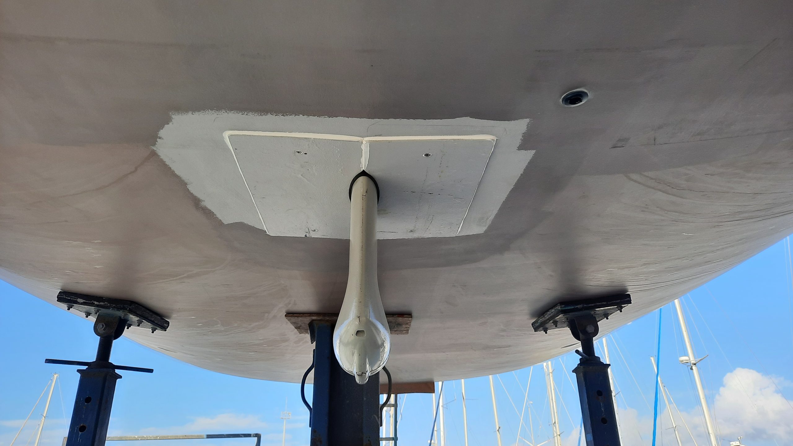
It is quite common to have fibreglass pieces made in order to cover the gap between the saildrive and hull. In our case, given the newly founded love for aluminium and extra pieces laying around, I made some covers from 4mm 5083T111 aluminium plate. The section around the leg was slightly curved from fwd to aft and the plates were dead flat. So, I used a 6mm countersunk bolt to hold each end until the ample amount of sikaflex 291 set. After it set I removed the bolts. Now, there is an ample, maybe more than ample amount of sikaflex but it’s better than too little and having the plates fall off. I say this now, but let’s see what is said when its time to remove the plates in the event of servicing the saildrive.